ZBrush modeling

3D sculpt inspired by mixed martial arts.

Space Switching Video Series

A video series explaining the concept and scripting a tool to setup and interact with space switching setup for rigs.

Rigid Bodies Simulation

Small project with simulated rigid bodies and nParticle effects.

Maya Muscle Tutorial

A tutorial on using the spline deformer on custom geometry to create muscle flexing and stretching behavior.

Sunday, August 11, 2013

Joint Relocation

In this post I want to show you a quick and easy way of reposing your joint layout to make it easier for you to reuse a skeleton if you already have one laid out that you want to reuse. The idea here is to be able to just worry about where the joint is positioned, and not have to worry about maintaining joint orientation.

To accomplish this we will rely mainly on one thing, and that is an aim constraint, to allow us to aim the rotation axis we want down the joint chain.

Ok, so to break it down, lets just start with a 3 joint chain. To visualize this better lets go ahead and turn Local Rotation Axis on for all joints.

By default we have the x axis going down the joints. To keep our joint intact we will use locators to actually move around the joints to reposition them. The aim constraints will be applied to these locators.

So we need to start by breaking up the joint hierarchy. Parent each to world, you can do that by hitting Shift + P with the joint selected.

We will then create a locator at each joints position. In fact we want to maintaing the joints orientation as well. So for each joint, select the joint, select the locator, and goto Constraint -> Parent Constraint. We want to uncheck maintain offset. That will position and orient the locators to match the joints. We can then delete the constraint, and parent the joint under the locator.


Now we go ahead and set the aim constraints. This will mimic our original hierarchy and allow us to keep the joint orientation.

Select the second locator and shift select the first locator. And goto Constraint -> Aim Constraint.
We can repeat the steps for the third and second locators.
We can now relocate the joints. When we are ready we can unparent the joints (Shift + P) and parent the joints back into the hierarchy.


We can then delete the locators, and everything we be gone with them.


And there we go! Now, obviously it wouldn't be too efficient to have to redo this every single time. So if you want, check out lpJointRelocation.py

And here is a quick overview of how to use it.

Break Hierarchy: This will break down the hierarchy, create locators and constraints, and hook up message attributes to manage the connections with the tool. Select the first joint in the hierarchy you want to adjust.

Rebuild Hierarchy: To put the joints back into the hierarchy in the new position. This will also get rid of the created nodes that are no longer required. Select the first locator.

Select Hierarchy: To make it easier to select all the joint in the hierarchy starting from the selected joint.

Toggle Local Axis: To toggle on and off the local rotation axis to help with some visual feedback.

Hope you guys find it useful!

Tuesday, August 6, 2013

Turning Off Local Rotation Axis

If you ever have been frustrated with the local axis toggle in maya like I once was you might find this little script useful. Sometimes you forget or loose track of what you've toggled on. Today I saw a friend spend so much time trying to figure out what node has local axis on, that while it was kinda of funny, I felt it couldn't be a bad thing to share something that can fix it in just a few lines. As I'm sure there are more people who have struggled with this at some point. So, using good old fashion MEL, you can just create a shelf button and copy these lines

// Turn off LRA for all the selected objects
$sl = `ls -sl`; for ($s in $sl) { $on = `toggle -q -localAxis $s`; if ($on == 1) { toggle -localAxis $s; } };
You can now select the objects you want and click the shelf button to run the code, and it will toggle only the ones that are on. Essentially making sure everything is off.

Saturday, August 3, 2013

Extracting Twist Controls for IK Spline

Being able to have twisting propagate down a joint chain is a common feature for character rigs. An automated approach over a manual approach might be a quicker and easier solution, however as we'll discuss below might end up presenting problems. A manual method of animating twisting in the other hand while giving exactly what the animator want, is also more work for the animator.  There are many ways to setup twisting, each with their own advantages and issues. However, this post won't be about the best solution for twisting, so much as it will be a practical solution for providing the animator with more control over the twist action of the joints by having both an automated and a manual solution.

I've tried many different setups and upon arriving at this solution I found it to be the most stable and practical for when dealing with twisting.

Watch the video demonstrating the setup here.

So let's get started. Before we start lets create a quick setup to try this out. The first thing we will need is a Spline IK driven joint chain. 


Next, we will need to make our IK controls. To keep everything simple for now, lets just use empty transform nodes for our controls. As an observation, this step isn't really necessary, we just want to have a way of driving the curve shape to drive the joint's position.

Let's start by making a single joint, group it twice and name the nodes,
GRP_Start_IK, CTRL_Start_IK, jnt_StartCurveDriver

Duplicate the top group and rename the new nodes,
GRP_End_IK, CTRL_End_IK, jnt_EndCurveDriver


Now we can move the corresponding groups to the start and end of the joint chain.


Finally we can select the driver joints and select the curve last, and goto Skin -> Bind -> Smooth Bind
we can then choose the following options


Now, we can drive the Spline IK with our controls. So this will be our starting point.

Notice that we can move and rotate our controls to drive the curve that is driving the joint chain. However, we can't seem to rotate the controls to get twisting. The reason for this is that components, such as the CVs on the curve only represent points in space, and because we don't get normals with curves, we can't get rotation information from the curve points. Now, some of you may be familiar with the Advance Twist Controls setup for spline IK. If not, you can check out the post here that goes over the setup.

The advance twist setup is nice to quickly get twisting with your Spline IK. However, we mentioned that we want to have not only the option to toggle auto twisting on and off, but to also offset the twisting. In addition we will also look at how this new setup will give us a nice solution for a common problem that comes with using the advance twist controls. Lets take a look now at how we can extract the twist from the spline IK solver and give it to the animator to control and give them the option to automate or not the twisting.

Lets start by creating some attributes on our end control to drive the twisting. Lets create an autoTwist and a twistOffset attribute.


We can now start creating and hooking up the math nodes to help us with this setup. The first thing we want to create is a multiplyDivide node to multiply the rotationX (that is our twist axis for our control in this case) of our end control by our autoTwist attribute value. Lets rename this md_autoTwist and hook up our attributes.

Connect CTRL_End_IK.rotateX to md_autoTwist.input1X
Connect CTRL_End_IK.autoTwist to md_autoTwist.input2X


Next we want to create a plusMinusAverage node to sum our twistOffset value to the output of the multiplyDivide node. So lets do that and rename this pma_twistOffset.

Connect md_autoTwist.outputX to pma_twistOffset.input1D[0]
Connect CTRL_End_IK.twistOffset to pma_twistOffset.input1D[1]


Finally, we are ready to connect it to our ikHandle.

Connect pma_twistOffset.output1D to ikHandle1.twist


There we go! So with not a lot of extra work, just 2 extra nodes we get a clean setup for twisting. And that is actually not the best part. I mentioned earlier that this setup would also help solve an issue of the advance twist control. Or with most automated solutions. And that is the flip that occurs at 180 degrees. This problems occurs because of how rotations are being calculated (Euler rotations). This ends up leading us into problems such as Gimbal locking and making the setup fragile if we are relying on any one rotation axis to get our twisting. So as it turns out its not so advance after all! :)

As this is another whole discussion in itself, I'll just leave it at that. For now, be assured that this setup will handle with no problems rotations beyond 180 degrees or -180 degrees for that matter with no problems because of how the spline IK is solving for twisting.

The setup in its current state is an example in which the twist propagates up the joint chain. However, what if we need the CTRL_Start_IK to also be able to control the twisting. To have the twisting propagate down the joint chain. Let's take a look at that.

If we go ahead and use the roll attribute on the ikHandle notice that the entire joint chain rotates. The obvious thing to do is to counter rotate using the twist and we then get the effect the rotation came from the start of the joint chain. 

So let's start with that first.

Connect CTRL_Start_IK.rotateX to ikHandle1.roll

Now, for the start control to work with the end control at the same time and for our autoTwist attribute to work on CTRL_Start_IK as well, we will create another multiplyDivide node, we can call this md_autoTwist2.

Connect CTRL_End_IK.autoTwist to md_autoTwist2.input1X
Connect CTRL_Start_IK.rotateX to md_autoTwist2.input2X

To counter rotate we will use a plusMinusAverage node. We will call this pma_twistOffset2. However, we also need to account for whatever twist offset already exists from the CTRL_End_IK.

Connect pma_twistOffset.output1D to pma_twistOffset2.input1D[0]
Connect md_autoTwist2.outputX to pma_twistOffset2.input1D[1]
Connect pma_twistOffset2.output1D to ikHandle1.twist

And we can set the operation to Subtract.


And there it is! Now go and have fun making your joints twist!

I realize although its not too complicated you probably don't want to have to setup it every single time. Hopefully you still were able to understand it so that you could :)

But to speed up the process here's a script to set it up for you. It takes in the start control, the end control, the control object, the ikHandle, and the twist axis for the control rotation (this can be negative as well).

import maya.cmds as cmds

def twist(startCtrl, endCtrl, ctrlObj, ikHandle, axis):
 '''
 Create twist control for the spline IK setup
  
  startCtrl : node controlling the start of the joint chain
  endCtrl  : node controlling the end of the joint chain
  ctrlObj  : control object to host the twist attributes
  ikHandle : the spline IK handle
  axis  : the rotation axis for twisting on the controls : "x", "y", "z", "-x", "-y", "-z"
 '''
 # check nodes
 for node in [startCtrl, endCtrl, ctrlObj, ikHandle]:
  if not cmds.objExists(node):
   cmds.error("%s does not exist." % node)
 # check axis
 if axis not in ["x", "y", "z", "-x", "-y", "-z"]:
  cmds.error("Invalid axis.")
  
 # check if our twist axis is on the negative side
 neg = False
 splitString = axis.split("-")
 if splitString[0] == "":
  axis = splitString[1]
  neg = True
 axis = ".r" + axis
 
 # create new attributes
 cmds.addAttr(ctrlObj, ln="autoTwist", at="double", dv=1, min=0, max=1, k=True)
 cmds.addAttr(ctrlObj, ln="twistOffset", at="double", dv=0, k=True)
  
 # create nodes for autoTwist and twistOffset
 autoTwist1 = cmds.createNode("multiplyDivide", n="md_" + ctrlObj + "_autoTwist1")
 autoTwist2 = cmds.createNode("multiplyDivide", n="md_" + ctrlObj + "_autoTwist2")
 twistOffset1 = cmds.createNode("plusMinusAverage", n="pma_" + ctrlObj + "_twistOffset1")
 twistOffset2 = cmds.createNode("plusMinusAverage", n="pma_" + ctrlObj + "_twistOffset2")

 # connect the end control
 cmds.connectAttr(endCtrl + axis, autoTwist1 + ".input1X")
 cmds.connectAttr(ctrlObj + ".autoTwist", autoTwist1 + ".input2X")
 
 cmds.connectAttr(autoTwist1 + ".outputX", twistOffset1 + ".input1D[0]")
 cmds.connectAttr(ctrlObj + ".twistOffset", twistOffset1 + ".input1D[1]")
 
 # connect the start control
 cmds.connectAttr(startCtrl + axis, autoTwist2 + ".input1X")
 cmds.connectAttr(ctrlObj + ".autoTwist", autoTwist2 + ".input2X") 

 cmds.connectAttr(twistOffset1 + ".output1D", twistOffset2 + ".input1D[0]")
 cmds.connectAttr(autoTwist2 + ".outputX", twistOffset2 + ".input1D[1]")
 
 cmds.setAttr(twistOffset2 + ".operation", 2) # subtract
 
 # connect to the ikHandle
 cmds.connectAttr(startCtrl + axis, ikHandle + ".roll")
 cmds.connectAttr(twistOffset2 + ".output1D", ikHandle + ".twist")
 
 # make changes if the twist axis is on the negative side
 if neg:
  invTwist1 = cmds.createNode("multiplyDivide", n="md_" + ctrlObj + "_invTwist1")
  invTwist2 = cmds.createNode("multiplyDivide", n="md_" + ctrlObj + "_invTwist2")
  
  cmds.setAttr(invTwist1 + ".input2X", -1)
  cmds.setAttr(invTwist2 + ".input2X", -1)
  
  cmds.connectAttr(endCtrl + axis, invTwist1 + ".input1X")
  cmds.connectAttr(startCtrl + axis, invTwist2 + ".input1X")
  
  cmds.connectAttr(invTwist1 + ".outputX", autoTwist1 + ".input1X", f=True)
  cmds.connectAttr(invTwist2 + ".outputX", autoTwist2 + ".input1X", f=True)
  cmds.connectAttr(invTwist2 + ".outputX", ikHandle + ".roll", f=True)

Hope you guys liked it! Feel free to share!
And to leave any comments or questions!

Enjoy!

Friday, August 2, 2013

Rigging the Eye Brows

Check out the video tutorial on rigging eye brow controls for your characters. For my friend Rafael Salvador who asked me to put this together.
Im also going to start embedding the videos here in the website and see how that goes.


This is the concept shown in the video.


Enjoy!

Tuesday, July 30, 2013

Practical Facial Rigging

In this post I'll be going over a face setup Im working on for a personal project. The idea behind this setup is to allow for quick and efficient facial rigging, by allowing a large level of control, from a large library of preset face shapes and individual face controls. This setup will also allow for easy transferability of the the rig across characters and with that, animation data across multiple face rigs.

Some of the concepts I'll be touching on were introduced by Jeremy Ernst for the Gears of War 3 game.

I mentioned a large library of preset face shapes. Yes, this means blendshapes, or morph targets, or whatever the software you use calls them. And lots of them. The idea is to make the facial animation easier and cleaner. By having many face poses broken down into separate groups, we can narrow down the animation of these poses to just one attribute control, instead of having to animate translations or rotations (and sometimes even scale depending on how little joints we are using on the face) to get the desired pose. Again, this keeps things a lot cleaner and simpler to animate (single animation curves in the graph editor).

This takes us next to how the poses are made. The pose library for the face will be built following the Facial Action Coding System. Individual poses will be sculpted to represent each action unit, and then used as blendshapes. Below are some links with more information if you want to learn more about it.

http://en.wikipedia.org/wiki/Facial_Action_Coding_System
http://www.cs.cmu.edu/~face/facs.htm
http://face-and-emotion.com/dataface/facs/description.jsp

To summarize, F.A.C.S outlines a series of action units that describe the face's range of motion through the contraction or relaxation of muscles in the face.

Although the current setup offers the animator a lot of intuitive control to drive the character's facial expressions, its still desirable to have individual controls to offset the preset poses. To allow for that, on top of the current setup there will also be a control rig, with individual controls for joints that are weighted on the face skin cluster. The interesting part however is to figure out how to have the controls follow the surface of the face while we are changing between different face poses. And this is where the concept of rivets comes in.

In essence, rivets allow you to pin something to something else, much like a point constraint, but at a component level. Meaning, the object will move with the point it is pinned to. Therefore, you can deform the object and the rivet will move to follow the deformation. Places for using rivets include surfaces (NURBS and Poly) and curves. Below I included a script for creating a locator pinned to a point on a surface or a point on a curve.
# import python modules
try:
    import maya.cmds as cmds
    import maya.OpenMaya as om
except Exception, e:
    print "Error while trying to import python modules."
    print "Exception: ", e

def rivetAtPointOnSurface():
    ''' Pin the object to selected points on the NURBS surface '''
    # get the selected components
    sel = cmds.ls(sl=True, fl=True)
    
    if not sel:
        cmds.error("Nothing selected")
        
    # get the surface name
    surface = sel[0].split(".")[0]
    # get the shape
    shape = cmds.listRelatives(surface, shapes=True)[0]
    
    # create rivet for each selected component
    for each in sel:
        # get the position to pin the object to on the surface
        pos = cmds.xform(each, q=True, ws=True, t=True)
        # define the point
        mPoint = om.MPoint(pos[0], pos[1], pos[2])
        # get the surface's dagPath
        selectionList = om.MSelectionList()
        selectionList.add(shape)
        mNode = om.MDagPath()
        selectionList.getDagPath(0,mNode)
    
        if cmds.objectType(shape) == "nurbsSurface":        
    
            surfaceFn = om.MFnNurbsSurface(mNode)
            util = om.MScriptUtil()
        
            uParamPtr = util.asDoublePtr()
            vParamPtr = util.asDoublePtr()
        
            if not surfaceFn.isPointOnSurface(mPoint):
                surfaceFn.getParamAtPoint(mPoint, uParamPtr, vParamPtr, False, om.MSpace.kObject, 0.001)
            else:
                mPoint = surfaceFn.closestPoint(mPoint, False, uParamPtr, vParamPtr, False, 0.001, om.MSpace.kObject)
                surfaceFn.getParamAtPoint(mPoint, uParamPtr, vParamPtr, False, om.MSpace.kObject, 0.001)
            
            # get the U and V paramters
            u = util.getDouble(uParamPtr)
            v = util.getDouble(vParamPtr)
    
            # create rivet locator
            rivet = cmds.spaceLocator(n="rivet")[0]
    
            # create point on surface node
            psi = cmds.createNode("pointOnSurfaceInfo", n="psi_" + surface)
            cmds.setAttr(psi + ".parameterU", u)
            cmds.setAttr(psi + ".parameterU", v)
            
            cmds.connectAttr(shape + ".ws", psi + ".is", f=True)
            cmds.connectAttr(psi + ".position", rivet + ".t", f=True)
            
            # constraint the rivet locator
            cmds.orientConstraint(surface, rivet, mo=True)
        else:
            cmds.error("Not a NURBS surface component")

def rivetAtPointOnCurve(curve):
    ''' Pin the object to the selected CVs '''
    # get the selected components
    sel = cmds.ls(sl=True, fl=True)
     
    if not sel:
        cmds.error("Nothing selected")
         
    # get the curve name
    curve = sel[0].split(".")[0]
    # get the shape
    shape = cmds.listRelatives(curve, shapes=True)[0]
     
    # create rivet for each selected component
    for each in sel:
        # get the position to pin the object to on the surface
        pos = cmds.xform(each, q=True, ws=True, t=True)
        # define the point
        mPoint = om.MPoint(pos[0], pos[1], pos[2])
        # get the surface's dagPath
        selectionList = om.MSelectionList()
        selectionList.add(shape)
        mNode = om.MDagPath()
        selectionList.getDagPath(0,mNode)
     
        if cmds.objectType(shape) == "nurbsCurve":       
     
            curveFn = om.MFnNurbsCurve(mNode)
            util = om.MScriptUtil()
         
            uParamPtr = util.asDoublePtr()
         
            if curveFn.isPointOnCurve(mPoint):
           curveFn.getParamAtPoint(mPoint, uParamPtr, 0.001, om.MSpace.kObject)
            else:
           mPoint = curveFn.closestPoint(mPoint, uParamPtr, 0.001, om.MSpace.kObject)
           curveFn.getParamAtPoint(mPoint, uParamPtr, 0.001, om.MSpace.kObject)

            # get the U paramter
            u = util.getDouble(uParamPtr)
     
            # create rivet locator
            rivet = cmds.spaceLocator(n="rivet")[0]
     
            # create pointOnCurveInfo node
            pci = cmds.createNode("pointOnCurveInfo", n="pci_" + curve)
            cmds.setAttr(pci + ".parameter", u)
             
            cmds.connectAttr(shape + ".ws", pci + ".ic", f=True)
            cmds.connectAttr(pci + ".position", rivet + ".t", f=True)
            # constraint the rivet locator
            cmds.orientConstraint(curve, rivet, mo=True)
        else:
            cmds.error("Not a NURBS Curve component")
Unfortunately with Maya's default nodes we can't attach an object to a point on a polygon. An idea by Michael Bazhutkin was to use the node curveFromMeshEdge to extract two curves from edges on a surface and use them to create a loft surface (a NURBS patch) and pin the rivet to the middle point on this surface.
def rivetAtPointOnMesh():
    ''' Pin the object to selected face on the NURBS surface '''
    # get the selected component
    sel = cmds.ls(sl=True, fl=True)

    if not sel:
        cmds.error("Nothing selected")

    # get the surface name
    surface = sel[0].split(".")[0]
    # get the shape
    shape = cmds.listRelatives(surface, shapes=True)[0]    
    # create rivet for each selected component
    for each in sel:
        # convert selection to edges
        cmds.polyListComponentConversion(each, ff=True, te=True)
    
        # create curves from edges
        edges = cmds.ls(sl=True, fl=True)

        if cmds.objectType(shape) == "mesh": 
    
            c1 = cmds.createNode("curveFromMeshEdge")
            cmds.setAttr(me1 + ".ihi", 1)
            cmds.setAttr(me1 + ".ei[0]", edges[0])
        
            c2 = cmds.createNode("curveFromMeshEdge")
            cmds.setAttr(me2 + ".ihi", 1)
            cmds.setAttr(me2 + ".ei[0]", edges[1])
            
            # create a lofted surface from curves
            loft = cmds.createNode("loft")
            cmds.setAttr(loft + ".ic", s=2)
            cmds.setAttr(loft + ".u", True)
            cmds.setAttr(loft + ".rsn", True)
            
            # create a pointOnSurfaceInfo node for center point on lofted surface
            psi = cmds.createNode("pointOnSurfaceInfo")
            cmds.setAttr(psi + ".turnOnPercentage", 1)
            cmds.setAttr(psi + ".parameterU", .5)
            cmds.setAttr(psi + ".parameterV", .5)
            
            cmds.connectAttr(loft + ".os", psi + ".is", f=True)
            cmds.connectAttr(c1 + ".oc", loft + ".ic[0]")
            cmds.connectAttr(c2 + ".oc", loft + ".ic[[1]")
            cmds.connectAttr(shape + ".w", c1 + ".im")
            cmds.connectAttr(shape + ".w", c2 + ".im")
            
            # create rivet locator
            rivet = cmds.spaceLocator(n="rivet")[0]
            cmds.connectAttr(psi + ".position", rivet + ".t", f=True)
            
            # constraint the rivet locator
            cmds.orientConstraint(surface, rivet, mo=True)
    
        else:
            cmds.error("Not a polygon mesh")
This works great, but doesn't let us create a rivet on a specific point on a polygonal mesh. For that we would need a plugin that works like the pointOnSurfaceInfo. But that's a subject for later.

Now that we have a way to track different positions on the face, we can use that information to move our controls. And yes, I did say track (with italics). Because in essence that is what we are doing, much like motion capture, we are tracking different positions on that face to be able to drive or controls, which are driving the face joints.

With that in mind, we just need to understand how all these things will be hooked up together. Let break this down.


To keep our face rig as clean as possible, we will have one blendshape target (Master Blendshape) piped into the final face mesh. All of the different blendshapes (from the F.A.C.S pose library) will be driving the Master Blendshape, and hence the final mesh. The rivet locators will be pinned to the Master Blendshape face. Because the rivets are only pinned to a position, we also need to constraint its rotation to that of the head so it follows it correctly. We can then drive the control's parent space with the rivet. We can do that with a parent constraint on a group above the control. And finally the joints are parent constrainted to the controls.

Cool. Now that we have covered the setup lets look at what we can further achieve with this setup.

Transferring Rigs

The idea is that you can use the same topology for various face meshes, and by applying the initial rig as a blendshape, we now have the rig working with a new face model.

Transferring Animation

Transferring animation data also becomes really easy. With the the pose library the animator will be animating attributes, and with the controls, offset transforms, which are relative and not based on world or parent space. Therefore we can transfer animation really easily between multiple face rigs with the same setup.

So that was an overview of the design. Hopefully that can inspire you to do something cool!

Thursday, July 25, 2013

Connect Attribute: Maintain Offset

Connecting attributes is one way to drive a node's attribute using another in Maya. When connecting numeric values, such as translate or rotate, sometimes an offset exists prior to the connection which you might not want to lose. It would be nice if we could maintain that offset when doing the connection between attributes, like we can with our standard constraints.

A simple way to do that is using a math node plusMinusAverage as a buffer. We can first calculate the difference between the two attributes we are connecting. For example, if we have A = < 0, 0, 0 >  and B = < 3, 1, 3 >  if we connect A to B directly, now B = < 0, 0, 0 >. What we can do to get around this is to first find the difference between A and B as A-B and then use our plusMinusAverage node to subtract this difference from A. We can first store the current value for the source attribute, A, in the first input, and set the other input to the difference we have just computed, in this case < -3, -1, -2 >. By default the node's operation is set to Sum, we want Subtract. We then connect the output to the destination attribute, and now the attributes are connecting but no 'snap' happened.

In this example I want to connect pCube2.translateY to pCube1.translateZ, but notice the pCube2.translateY is 0 while pCube1.translateZ is 3.

If I do a simple connection, pCube1 will 'snap' to the origin.


We might not want that. So we do this setup to keep that offset.


Here is a wrapper for Maya's connectAttr command allowing to maintain the current offset by using a plusMinusAverage node in between.

UPDATED
def connectAttr(srcPlug, destPlugs, maintainOffset=False, **kwargs):
    ''' Wrapper for Maya's connectAttr command with the extra functionality of allowing to maintain offset
        if attribute is a numeric attribute and to connect to multiple objects '''
    if type(destPlugs) != list:
        destPlugs = [destPlugs]
    
    srcValue = cmds.getAttr(srcPlug)

    for destPlug in destPlugs:
        if maintainOffset:
            # get the attribute type
            attrType = cmds.getAttr(srcPlug, type=True)
            
            destValue = cmds.getAttr(destPlug)
            
            if attrType in ["doubleLinear", "doubleAngle", "double", "long", "float"]:
                # find the difference 'delta' between the two attributes    
                diff = srcValue - destValue
                # create a node to keep the offset
                offsetNode = cmds.createNode("plusMinusAverage")
                cmds.setAttr(offsetNode + ".operation", 2)      # subtract
                
                # connect and disconnect plug to get the value in
                cmds.connectAttr(srcPlug, offsetNode + ".input1D[0]")
                cmds.connectAttr(srcPlug, offsetNode + ".input1D[1]")
                cmds.disconnectAttr(srcPlug, offsetNode + ".input1D[1]")
                cmds.setAttr(offsetNode + ".input1D[1]", diff)
                
                cmds.connectAttr(offsetNode + ".output1D", destPlug, **kwargs)
            
            elif attrType in ["double3", "float3"]:
                # find the difference 'delta' between the two attributes    
                diff = []
                for i, d in enumerate(srcValue[0]):
                    diff.append(d - destValue[0][i])
                
                # create a node to keep the offset
                offsetNode = cmds.createNode("plusMinusAverage")
                cmds.setAttr(offsetNode + ".operation", 2)      # subtract
                
                # connect and disconnect plug to get the value in
                cmds.connectAttr(srcPlug, offsetNode + ".input3D[0]")
                cmds.connectAttr(srcPlug, offsetNode + ".input3D[1]")
                cmds.disconnectAttr(srcPlug, offsetNode + ".input3D[1]")
                cmds.setAttr(offsetNode + ".input3D[1]", diff[0], diff[1], diff[2])
                
                cmds.connectAttr(offsetNode + ".output3D", destPlug, **kwargs)
                
                return offsetNode
        else:
            cmds.connectAttr(srcPlug, destPlug, **kwargs)
Hope you guys find this useful.

Wednesday, July 24, 2013

Lattice Fun: Correctives

I wanted to do this quick post to remind some of you the power of lattices when it comes to quickly shaping geometry. The workflow I'll be going over in the example below covers an quick and easy technique for creating some pose space deformations. Do keep in mind however, that while this technique is great for deformations on single axis rotations, in areas that allow for multi axes rotations we would need a more advance approach.

You can also watch here the video example for setting this up.
So let's get started.

I'll be using a simple polygonal cylinder to demonstrate this. So go ahead and create a cylinder.
Give it enough resolution so we can deform this properly.


Next lets create some joints for skinning the geometry to.


Now, lets go ahead and create a lattice to deform the cylinder. Select the cylinder, and goto
Create Deformers -> Lattice 


Give the lattice enough resolution to deform the geometry properly. Think about the shape you want to achieve and how many control point spans you might need. I changed the divisions along the height to 9, that way I'll have 3 control spans in the midsection of each bone, and that will give me enough control. Play around with these values and see what suits your needs for what you have in mind.


This is where this gets fun. We now want to bind the lattice to the joints, so Select the first joint, Shift Select the lattice and goto
Skin -> Bind Skin -> Rigid Bind (at default settings -> it will use the joint's hierarchy)

Note: We could have used the Smooth Bind instead. However, we are looking for easy control of shaping, and when we begin tweaking the lattice to shape our corrective, you'll notice that the smoothing from the Smooth Bind can get in the way. We Rigid Bind the tweaking are more precise.

Great. Now test out the setup by rotating the mid joint.

Right now, the deformation is a little rough however, so to get a better starting point.
Change the Local Influence in the ffd1 node (located under the lattice's OUTPUTS).


The skinning should be smoother now (see, and we are not even using Smooth Bind!) :)

The last step is just modifying our lattice to give us the desired shape on the geometry that we want.
Before you do this, just figure out how you plan on using this new shape. You can use it for a BlendShape target for example by duplicating the new geometry and getting rid of the lattice. Or you could just leave the lattice and use Set Driven Keys using the joint's rotation to drive the lattice's control point's position.

If your going with the second option, make sure you you set a key on the Set Driven Key window before you start tweaking the lattice points. Select all latices points and click Load Driven, select the mid joint and click Load Driver.


And thats it!

Now go have fun using lattices!

Tuesday, July 23, 2013

Enhancing your Stretchy IK

In response to some questions about the stretchy IK setup I describe in this post, I will be going over extra functionality that you could add to that kind of setup to make it more robust. So, since I'll be expanding on the concepts from the other post, I suggest you just quickly go over it if your not yet familiar with this kind of setup.

Global Scale

Lets start with something simple. Allowing your rig to scale is usually a good idea. If we are using the stretchy IK as a smaller component of a rig, we need to make sure it will scale uniformly with the rest of the rig. We can start by looking at our distanceShape node. We are using distance measurements to get this setup to work, however, our translation values from joint to joint does not change when we scale the whole rig up. Therefore we need to factor in the global scale value. We do this by dividing the distance from the distanceShape node by the global scale.

We can start by creating a multiplyDivide node. Lets set the operation to divide. And next, we want to connect the distance attribute to input1X and our global scale attribute to input2X.

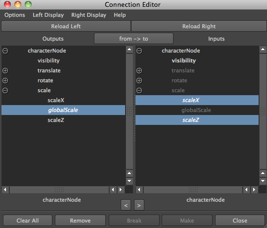
As a tip, to create and use an alias for the scale attribute on the character node that will be scaling the entire rig, you can use the following mel command,

aliasAttr globalScale characterNode.scaleY

You can then connect the other two scale attributes to the new globalScale attribute. Then you can hide them if you'd like.


Finally you can connect outputX on the multiplyDivide node to what was initially connected to the distance attribute.

Here is a script you can use to create and connect the global scale multiplyDivide node. It takes an inPlug string, an outPlugs list, and a scaleDriver string.

For example,

inPlug = 'distanceShapeNode.distance'
outPlugs = [ 'conditionNode.firstTerm', 'conditionNode.colorIfTrueR' ]
scaleDriver = 'characterNode.globalScale'
def createGlobalScaleNode(inPlug, outPlugs, scaleDriver):
    ''' Create node to allow setup to scale globally '''
    globalScaleNode = cmds.createNode("multiplyDivide")
    
    cmds.setAttr(globalScaleNode + ".operation", 2) # Divide
    cmds.connectAttr(inPlug, globalScaleNode + ".input1X", f=True)
    cmds.connectAttr(scaleDriver, globalScaleNode + ".input2X", f=True)
    
    for plug in outPlugs:
        cmds.connectAttr(globalScaleNode + ".outputX", plug, f=True)
    
    return globalScaleNode

Auto Stretch Toggle

With the current stretchy IK setup we are stretching it automatically. Something that's always nice to have if your automating any kind of controlled movement, is to allow the animator to turn that automation off if he chooses to. So lets go ahead and create a toggle for that.

Once again, start by creating a multiplyDivide node. This time lets leave the operation as multiply. Next we will need to create an actual attribute to toggle the stretch on and off.

Add a new attribute to the IK control node, autoStrech.

As a tip, I like to create any type of switch control as an integer instead of a boolean. The reason for this is that from experience the fact that you cannot middle mouse drag the boolean attribute to switch values can get annoying after awhile. So I prefer using an integer from 0 to 1 so you can easily scrub the value on and off. But that's up to you.

Now, we can connect the attributes. Lets go ahead and continue from where we left off in the last section.

We can connect the outputX from the global scale multiplyDivide node to input1X and then connect the autoStretch attribute on the IK control to input2X. The result of this multiplication will be either 0 or the divided distance itself. We can then pipe the outputX into the secondTerm attribute on condition node that we already had in place from the original setup. Because the condition operation is set to greater or equal, when our toggle is off, we will have original length >= 0 return True, and output the original distance, which is correct. The setup now works for when auto stretch is on or off.


Pole Vector Stretch

As we know our IK joints can either use a Single Chain or a Rotate-Plane solver. In the case of the RP solver we can use a polevector constraint. This next setup is a nice feature to give your character rig for example if it has arms and it needs to be able to plant its elbow on something and move his forearm freely. Allowing to stretch the mid joint to the PV object can let you place the polevector ( and therefore the elbow ) wherever you wish and then animate the lower arm without affecting the upper arm.

How do you go about doing that? Well the setup is a little more intricate. That's why I'll also be going over it in this video here. Hopefully it will help you understand the setup a little better.

We will first start by creating two extra distance nodes. One from the startJoint to the polevector object (we'll call this upper distance), and another from the polevector object to the endJoint (we'll call this lower distance).

Next, lets go ahead and create on our IK control a pvStretch attribute. This time we can make it a float from 0 to 1.

Now we need to create a blendTwoAttr node. This node will allow us to blend between two attribute values. Lets start with the mid joint (in an character rig example, this would be the character's elbow joint). For the mid joint we want to blend between the stretch node and the upper distance. This means the joint will either stretch with the IK control or will stretch to meet the distance from the start joint to the pole vector object.

Note:  The same rule applies here if we want to be able to make this setup scalable. We just need to divide these distances by the global scale.

The stretch node will vary depending on the stretch method you are using. If we're stretching the joints using scale then our stretch node is the stretchFactor multiplyDivide node. If translate, then our stretch node will be the stretchMultiply multiplyDivide node.

Next we need to make sure we connect our pvStretch attribute to the attributeBlender attribute on the blendTwoAttr node. Finally, we can connect the output to the joint's stretch axis. Again, this will depend on the stretch method being used and also the joint's orientation. For example, if we are stretching using translation and x is going down the joint (default), then we want to connect to the joint's translateX attribute.

From here we simply repeat the process for the end joint, and blend between the stretch node and the lower distance.

Great! No we have a pvStretch attribute that allows us to stretch our mid joint to the polevector object from any position (stretched or not).

To make the setup process a little quicker, here is a little script to create and connect the blendTwoAttr node. It takes an inPlugs list, an outPlug string, and a blenderPlug string.

For example,

inPlugs = [ 'stretchFactorNode.outputX',  'upperDistanceNode.distance' ]
outPlug = 'joint.StretchAxis'
blendPlug = 'ikCtrl.pvStretch'
def createBlendAttrNode(inPlugs, outPlug, blenderPlug):
    ''' Create node to support PV stretch '''
    # create blendTwoAttr nodes
    blendAttrNode = cmds.createNode("blendTwoAttr", n="%s_blendAttr" % blenderPlug)
    
    # connect nodes
    for i,plug in enumerate(inPlugs):
        cmds.connectAttr(plug, blendAttrNode + ".input[%d]" % i, f=True)
    
    cmds.connectAttr(blenderPlug, blendAttrNode + ".attributesBlender", f=True )
    cmds.connectAttr(blendAttrNode + ".output", outPlug, f=True)
    
    return blendAttrNode

You can also check out the download page here, for the latest update on the stretchyIkChain tool, which incorporate these new features with a simple gui, but also allows for easy access to the backend for creating the setup from command line.

Thursday, July 11, 2013

Using Python Iterables

Lets take a look at how we can use iterables in our workflow when rigging for writing procedural methods or classes. Im talking rigging modules, custom nodes, tools, etc..

Lets first understand what are iterables.

Iterables

The idea of iteration can be easily seen in a for loop where we read the items in a list one by one and print them.
numbers = [1, 2, 3, 4, 5]
for i in numbers:
    print i
Result:
1
2
3
4
5

The list numbers is an iterable. When you instance a list through list comprehension you are creating an iterable.
numbers = [x * x for x in range(5)]
for i in numbers:
    print i
Result:
0
1
4
9
25

Other examples of iterables are strings, files, dictionaries, etc... Iterables are useful because they can be read as often as you want.

To further understand iterables lets discuss generators.


Generators

Generators are what we call iterators. These we can only iterate over one time. The reason for this, is because unlike iterables that store the values in memory, generators create the values when they are queried.
numbers = (x*x for x in range(5))
for i in numbers:
    print i
Result:
0
1
4
9
25

Notice here we use parenthesis () and not brackets [ ]. Once we iterate over these values, we are done, we can't iterate read it again.

Finally we can take a look at yield.

Yield

Yield is a function that behaves similar to a return call. However, what it returns is a generator.

This is nice because now if we can iterate over all nodes in the current scene that fit a specific requirement for example. 

Lets iterate over all 3 joints in the scene:
import maya.cmds as cmds
def iter():
    for node in cmds.ls(type="joints"):
        yield node

joints = iter()

for joint in joints:
    print joint
Result:
joint1
joint2
joint3

If your writing your own class that creates a custom node (usually accompanied by an identifier under a  custom attribute) you can write a class method to iterate over all custom nodes in the scene with something like this:
@classmethod
def iter(cls):
    for node in cmds.ls(type="network"):
        if cmds.attributeQuery("type", exists=True, node=node):
            if cmds.getAttr(node + ".type") == cls.TYPE:
                yield cls(node)

In this case the example class will create a custom node of type network and it searches for a custom attribute as an identifier called type. The class has an attribute TYPE. We've found our custom node if the node attribute value matches the value in TYPE.


Wednesday, July 10, 2013

Tips n Tricks: Managing skin cluster weights

In this post I'll go over how you can code something to get and set skin cluster weights in Maya. We'll also discuss different things you can do to improve performance, especially if were working with a high resolution model. What will be covered here can be done using the API for more efficiency and better performance. But first we will go over simply using maya.cmds

Our first order of business is to look at how we can query the weights in a skin cluster on a vertex base and parse this information to store in an organized manner that we can use later.

If you search around you'll find than many people suggest using MFnSkinCluster.getWeights method. In its defense it is the fastest to query a high resolution mesh with many influences. However, it return weights for all influences, and as you may already know, not all influences are use for every vertex in the skinCluster, having weight of 0, so you end up with a lot of unnecessary data. Since this stage of querying the weights is to give us data to use later, wether we will be normalizing, modifying, or what have you, when we actually have to iterate through all this 'empty' data there will be a drastic decrease in performance time.

In this example, we will take a look at the skinCluster node itself. The next thing is very important to understand. The node has an attribute called weightList. This attribute has indices based on the vertex id for the mesh. For each index, there is another attribute called weights.


This attribute has index based on the influence object id, and each of these store a weight value for the vertex | influence combination.

Here is some code to query the vertex weights for the skin cluster:
def getSkinWeights(skinClusterName):
    ''' Get the weights per vertex on the meshName with the skinClusterName
    '''
    # to store the weight information
    # the key represents the vertex id and the value another dictionary
    # with keys representing the influence object id and the the value the weight as a double
    # Format: {vertexId: {influenceId: weight, ...}, ...}
    weights = {}
 
    # get the Influence Objects 
    influenceObjects = cmds.skinCluster(skinClusterName, q=True, weightedInfluence=True)
 
    # get the size of the vertex weight list
    weightListSize = cmds.getAttr(skinClusterName + ".weightList", size=True)

    # build weight dictionary
    for vertexId in range(0,weightListSize):
        # to store vertex weights
        vertexWeights = {}

        for influenceId in range(len(influenceObjects)):
            weight = cmds.getAttr(skinClusterName + ".weightList[%d].weights[%d]" % (vertexId,influenceId))
            # only store non-zero weights
            if weight != 0:
                vertexWeights[influenceId] = weight

        # store the weights for the vertex id
        weights[vertexId] = vertexWeights
 
    return weights

Notice I opted for using a dictionary. The way you want to store the data is up to you really. However, dictionaries are really powerful for this sort of thing. We can quickly access data based on the id, and it works great since we can query only the verts we choose to.

With the weights stored we can now turn to how we can set the weights. Once again, if you look, you'll find that using MFnSkinCluster.setWeights is a popular method and fast. But since we opted to query the weights in our own method, we can now quickly set our weight values using cmds.setAttr. In addition, what is really nice is that we also get undo which we don't with setWeights. Trust me this is a really nice feature.

So we've covered how to query the skin weights. After which you can modify the weight values however you wish. Then we can set the weights back to the skinCluster.

Here is some code to set the vertex weights to the skin cluster:
def setSkinWeights(skinClusterName, weights):
    ''' Set the modified weights to the skinClusterName.
    '''
    for vertexId in weights:
        # get influence dictionary
        influenceDict = weights[vertexId]

        # check if vertex is weighted - if there are any influence objects
        if influenceDict.items():
            for influenceId in influenceDict:
                plug = skinClusterName + ".weightList[%d].weights[%d]" % (vertexId,influenceId)

                # set the weight
                weight = influenceDict[influenceId]
                cmds.setAttr(plug, weight)

Its good to point out that this method will set the new weights fine, however it wont check for your if the weights add up to 1, if the weight value is positive, if the influence object doesn't exist, and other possible errors. So its a good idea to have checking method to take care of these things. As far as checking if the weights add up to 1, its an option to normalize them after you've modified them. The cmds.skinPercent has a normalize flag for that. I've noticed that when normalizing the weights while the script is running causes undesired results on vertices that haven't been assigned their new weight values.

This method of using setAttr is already faster than skinPercent, and can be faster depending on what you plan on doing with it, can be faster than MFnSkinCluster as well. Lets just expand our method to be a little more robust.

You could also use prune small weights, also in skinPercent, before setting the new weights to remove all zero weights.

Hero is the modified code to allow us to do just that:
def setSkinWeights(skinClusterName, weights, meshName, nonZero=True):
 ''' Set the modified weights to the skinClusterName. The nonZero flags assures that
  only nonZero weights are set.
 ''' 
 for vertexId in weights:
  # get influence dictionary
  influenceDict = weights[vertexId]

  # check if vertex is weighted - if there are any influence objects
  if influenceDict.items():
   for influenceId in influenceDict:
    if nonZero:
     influenceObj = cmds.listConnections("skinCluster1.matrix[%d]" % influenceId)
  
     if influenceObj:
      influenceObj = influenceObj[0]
    
      cmds.setAttr(influenceObj + ".liw", 0)
  
     # prune small weight values
     # need to turn off normalize to use prune
     plug = skinClusterName + ".normalizeWeights"
     normalize = cmds.getAttr(plug)
     if normalize:
      cmds.setAttr(plug, 0)
  
     cmds.skinPercent(skinClusterName, meshName, nrm=False, prw=.01)
     
     # return normalizing to what it was
     if normalize:
      cmds.setAttr(plug, normalize)
   
    plug = skinClusterName + ".weightList[%d].weights[%d]" % (vertexId,influenceId)

    # set the weight
    weight = influenceDict[influenceId]
    cmds.setAttr(plug, weight)